- My Forums
- Tiger Rant
- LSU Recruiting
- SEC Rant
- Saints Talk
- Pelicans Talk
- More Sports Board
- Coaching Changes
- Fantasy Sports
- Golf Board
- Soccer Board
- O-T Lounge
- Tech Board
- Home/Garden Board
- Outdoor Board
- Health/Fitness Board
- Movie/TV Board
- Book Board
- Music Board
- Political Talk
- Money Talk
- Fark Board
- Gaming Board
- Travel Board
- Food/Drink Board
- Ticket Exchange
- TD Help Board
Customize My Forums- View All Forums
- Show Left Links
- Topic Sort Options
- Trending Topics
- Recent Topics
- Active Topics
Started By
Message
Electrical Engineers, how do you properly power an LED on a spinning motor?
Posted on 10/29/21 at 1:29 pm
Posted on 10/29/21 at 1:29 pm
got a brain buster for you...
So if you saw my thread on the movie board about the Ghostbusters: Afterlife Proton Pack, you should go check it out. Anyway, I bought one, but I won't see it until Spring 2023. However, I'm starting on some mod plans for it.
The toy/replica cyclotron has a non-functioning motor in it with 4 separate LEDs that turn off/on at each lense on the cyclotron. This simulates that the cyclotron is "spinning". What I want to do is put a real DC motor inside with a spinning LED. I'll probably dress it up to make it look like a real cyclotron, but I'll worry about that later. I just want the basic functionality of how to make it work.
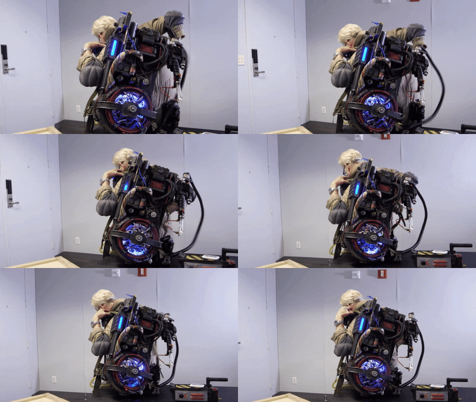
Below is a picture of the movie prop Adam Savage filmed while on the movie set, and you can see how the prop guys did it, which is the way I want to do it. I just don't know how. In my mind, the wires would wrap around the motor and shaft (obviously wrong). Can you look at the picture below and and make it out?

4 individual bulbs (GB '84)

Splinning/single bulb (GB:AL '21)

Here's what the guts of the toy/replica will look like. It's all plastic so that entire motor is fake:

So if you saw my thread on the movie board about the Ghostbusters: Afterlife Proton Pack, you should go check it out. Anyway, I bought one, but I won't see it until Spring 2023. However, I'm starting on some mod plans for it.
The toy/replica cyclotron has a non-functioning motor in it with 4 separate LEDs that turn off/on at each lense on the cyclotron. This simulates that the cyclotron is "spinning". What I want to do is put a real DC motor inside with a spinning LED. I'll probably dress it up to make it look like a real cyclotron, but I'll worry about that later. I just want the basic functionality of how to make it work.
Below is a picture of the movie prop Adam Savage filmed while on the movie set, and you can see how the prop guys did it, which is the way I want to do it. I just don't know how. In my mind, the wires would wrap around the motor and shaft (obviously wrong). Can you look at the picture below and and make it out?

4 individual bulbs (GB '84)

Splinning/single bulb (GB:AL '21)

Here's what the guts of the toy/replica will look like. It's all plastic so that entire motor is fake:

This post was edited on 10/29/21 at 1:31 pm
Posted on 10/29/21 at 2:05 pm to finchmeister08
I would probably make a 2 bladed "fan". One blade holds a battery the other is the LED on the end. You'd need to add a small switch, as well, so you can turn the LED on and off.
The other option is to power the LED the way a motor works. You have two rings around the motor that have the + and - voltage. Then the LED shaft would need brushes that run on the metal rings to conduct the electricity.
I personally would scrap the spinning LED all together. Get some addressable LEDs and put them in a ring. Then you can have the LEDs "spin" around. You could have trailing LEDs fade out so it looks like the light is spinning.
Posted on 10/29/21 at 2:30 pm to mchias1
those are some good ideas. the point of the spinning though is to also provide a "vibration" feature.
Posted on 10/29/21 at 2:31 pm to finchmeister08
quote:Looks like he used an LED ring in this build, eh?
In my mind, the wires would wrap around the motor and shaft (obviously wrong). Can you look at the picture below and and make it out?
Posted on 10/29/21 at 2:36 pm to finchmeister08
quote:I'd just put a separate vibe motor. That way you can do lights with no vibe if you want, and also tune the vibe and light speed independently.
the point of the spinning though is to also provide a "vibration" feature.
Posted on 10/29/21 at 2:57 pm to Korkstand
quote:
Looks like he used an LED ring in this build, eh?
yeah, this is what his finished product looked like.

Posted on 10/29/21 at 5:50 pm to finchmeister08
If you want to power something spinning, you can go with a brush/collector ring setup or a slip ring connection.
This post was edited on 10/29/21 at 5:56 pm
Posted on 10/29/21 at 7:03 pm to Dam Guide
quote:
If you want to power something spinning, you can go with a brush/collector ring setup or a slip ring connection.
And there it is folks.
Posted on 10/31/21 at 3:17 pm to Dam Guide
quote:
If you want to power something spinning, you can go with a brush/collector ring setup or a slip ring connection.
Came to post this, but the addressable LED ring would probably be easier and work better honestly.
Posted on 11/1/21 at 8:34 am to finchmeister08
quote:
the point of the spinning though is to also provide a "vibration" feature.
A weak fan would destroy itself pretty quickly.
I like the separate vibration motor idea.
You could take the fan from something like this:

ETA: And I'm sure this was for a costume and I'm late to the party. Tis my life.
This post was edited on 11/1/21 at 8:36 am
Posted on 11/1/21 at 10:30 am to finchmeister08
quote:
the point of the spinning though is to also provide a "vibration" feature.
Get a simple DC motor and put offset counter weights on it like a PS or X-box controller. Like a bigger version of these....

Posted on 11/1/21 at 1:00 pm to finchmeister08
Cars have clocksprings for stuff like this. I dunno if that's relevant.
Posted on 11/1/21 at 10:16 pm to shawnlsu
quote:
And I'm sure this was for a costume
nah, just a tinkering hobby. i plan on making it a wall mount for my office. a conversation starter for when/if i ever have friends over.
This post was edited on 11/1/21 at 10:23 pm
Posted on 11/2/21 at 4:20 pm to finchmeister08
Brush/collector setup is easiest.
Rotary transformer is a more complicated option, but has the advantage of no contact points.
Rotary transformer is a more complicated option, but has the advantage of no contact points.
Posted on 11/2/21 at 9:36 pm to Unobtanium
can someone explain to me how this dual DC motor setup sends a charge to the LED? is the second motor acting as a generator of some sort?
LINK
LINK
Posted on 11/3/21 at 6:18 am to finchmeister08
Yes the top motor is a generator. That's why he had to add the qtips to keep the top motor from just spinning with the bottom motors axle.
Posted on 11/3/21 at 8:37 am to mchias1
how does it generate power if both the motor and input shaft is spinning?
Posted on 11/3/21 at 8:51 am to finchmeister08
The q-tips provide enough drag so the motor spins slower than the shaft.
Posted on 11/6/21 at 7:10 am to finchmeister08
You can also look up a “Bob Blick Clock” setup. But that will take some programming and may be more than you are looking for. But this is along the lines of the brush/collector ring setup.
Popular
Back to top

 4
4


