- My Forums
- Tiger Rant
- LSU Recruiting
- SEC Rant
- Saints Talk
- Pelicans Talk
- More Sports Board
- Fantasy Sports
- Golf Board
- Soccer Board
- O-T Lounge
- Tech Board
- Home/Garden Board
- Outdoor Board
- Health/Fitness Board
- Movie/TV Board
- Book Board
- Music Board
- Political Talk
- Money Talk
- Fark Board
- Gaming Board
- Travel Board
- Food/Drink Board
- Ticket Exchange
- TD Help Board
Customize My Forums- View All Forums
- Show Left Links
- Topic Sort Options
- Trending Topics
- Recent Topics
- Active Topics
Started By
Message

 1
1


Posted on 8/21/23 at 6:39 am to Lonnie Utah
quote:
But D sized engines on green plastic army trucks launched horizontally on the street, AWESOME.
For real excitement remove the clay and the 'ejection charge' from the top of the motor, replace with tightly packed black powder, seal it in with a bit of cardboard and wax...
Posted on 8/26/23 at 10:19 pm to dakarx
Well we lost a payload out of one of our rockets today. Nose cone came off the payload section. We found the nose cone, but not the altimeter. Went back after dark to see if the leds were still lit, but i guess the 40 mah died long before we got back. Or it landed in one of the yards to the south of where we launch.
Posted on 1/13/25 at 8:09 am to Lonnie Utah
quote:
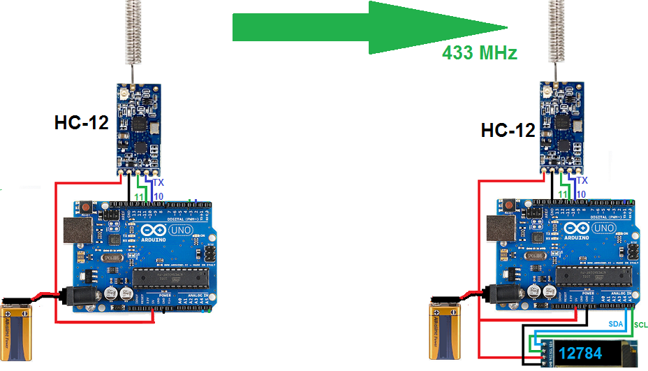
A small microprocessor connected to a Barometric pressure sensor, a GPS unit and an HC-12 433 mhz wireless board. If there's room I'd love to log the data via a microSD card, but if the boards are communicating with each other there should be a way to download it to the base station or to the microcontroller itself.
I had put this project on the back burner for a while, but started messing with it again last week. Yesterday, I was able to do wireless serial communication between two Arduinos over distances approaching 1/4 a mile. However, I was not able to send any GPS data. Plugging the unit into the computer told me I was not receiving any GPS data over the GPS module. So I still have some troubleshooting to do there. But sending wireless text messages was a big obstacle...
Here is a base station prototype receiving signals from the GPS transponder located outside. The only thing it's connected to is USB power.

This post was edited on 1/13/25 at 8:12 am
Posted on 1/15/25 at 10:52 pm to Lonnie Utah
Well, i got the GPS figured out, but can't get the two devices to\ talk to each other.
This post was edited on 1/16/25 at 1:08 pm

Posted on 1/16/25 at 1:31 pm to Lonnie Utah
Assuming the GPS just broadcasts nmea183 messages serially to your device?
How are you transmitting the serial data wirelessly? Using some sort of converter? Did you flip tx/rx
How are you transmitting the serial data wirelessly? Using some sort of converter? Did you flip tx/rx
Posted on 1/16/25 at 2:24 pm to UltimaParadox
I'm using the HC12 433MHz Serial Port Communication Module. I'm sure the issue is in the code (most likely the pinouts) as I had the HC12's working earlier this week.
Posted on 1/18/25 at 8:57 am to Lonnie Utah
Quick googling looks like the HC-12 boards are using the AT command sets, which kind of sucks. So not a really like a virtual com port.
Posted on 1/18/25 at 10:00 pm to UltimaParadox
quote:
Quick googling looks like the HC-12 boards are using the AT command sets, which kind of sucks. So not a really like a virtual com port.
Yeah, they are serial communication only. I found this out the hard way today after tinkering with it most of the afternoon. I was finally successful in making it work on the prototype bread board(s).
The problem was both the GPS module and the HC12 use the same software serial protocol. Even though I had software serial assigned to different digital pins, they still interfered with each other. Basically you could only use 1 at a time. So after much pondering on how to rectify the situation, I was able to force the HC12 to use the Arduino's hardware serial port. After I was able to figure that out, my biggest challenge was able to format the LCD display. I was able to cobble together a less than optimum, but workable solution.
The next task will be able to shrink things down to a "flyable" package and to test it in the field. Stay tuned...
Posted on 1/31/25 at 8:27 am to Lonnie Utah
Got the code working between the receiver and base station. It will send GPS location, current altitude and max altitude. It writes a bunch more stuff to and onboard micro-SD card. I had originally hoped to do onboard data storage, but when the sketch takes up 95% of on board storage, that wasn't a possibility. 
We did a real world test and were able to get a signal in excess of 1/3 a mile away. For our low powered rockets that should be fine. We were also in a residential neighborhood without great line of site. When we get to the desert with not obstructions, I would expect improved performance.
designed and ordered this guy yesterday.


ETA: His scout troop decided to do a "Rocket Launch Campout" this spring. We're going to camp near the Bonneville Salt Flats where you're cleared to launch up to 10,000'. The kid got a rocket design kit for Christmas and we're using it to build a two stage F engine powered rocket called "the Full Send". It should go close to 2,000' high and reach speeds in excess of 200 mph...

We did a real world test and were able to get a signal in excess of 1/3 a mile away. For our low powered rockets that should be fine. We were also in a residential neighborhood without great line of site. When we get to the desert with not obstructions, I would expect improved performance.
designed and ordered this guy yesterday.
ETA: His scout troop decided to do a "Rocket Launch Campout" this spring. We're going to camp near the Bonneville Salt Flats where you're cleared to launch up to 10,000'. The kid got a rocket design kit for Christmas and we're using it to build a two stage F engine powered rocket called "the Full Send". It should go close to 2,000' high and reach speeds in excess of 200 mph...
This post was edited on 1/31/25 at 8:48 am
Posted on 2/3/25 at 3:37 pm to Lonnie Utah
It was bad weather here this weekend so "Stuck" in the house so I got to thinking. The cables on our launch controllers are about 25' long, but the small hand held ones we have from Estes are only 15'. TECHNICALLY, for D's, E's and F's you should be 30 or more feet away. We're just under that. Now I know the "rocket police" won't say anything, but if we have 20-30 kids on a camp out, I want them pretty far back.
So I have a few NodeMCU's and D1 mini's hanging around from WLED projects. Why couldn't I write a couple of sketches for the wifi microcontrollers that I have, 1 setting up a wifi network and the other accessing it. One microprocessor could records a button push (signifying time to launch a rocket) and the other could receiver the signal and trigger a relay that would energize and fire the infighter.
So I got to work and in about an hour had a working proto-type. We tested it in the Cul-de-sac and at 100+' range we stopped the test because it was enough distance for our needs...
Posted on 2/18/25 at 2:03 pm to Lonnie Utah
The boards came in last week. Got a couple of them soldered up over the weekend. Took them for a test flight yesterday and they worked perfectly.

Edited to add a pic of the base station:

Edited to add a pic of the base station:
This post was edited on 2/18/25 at 3:12 pm
Posted on 2/25/25 at 11:35 pm to Lonnie Utah
Working on a wireless model rocket launch controller.
I hot the code working and theb prototype built. It is based on esp42 and uses a d1-mini and a nice mcu. The d1 mimi creates a wifi network. A button push on the sender is transferred wirelessly between the two units. The kid tested it last night about 500' of range.
I hot the code working and theb prototype built. It is based on esp42 and uses a d1-mini and a nice mcu. The d1 mimi creates a wifi network. A button push on the sender is transferred wirelessly between the two units. The kid tested it last night about 500' of range.
Posted on 2/26/25 at 8:23 am to Lonnie Utah
You can get a 433Mhz wireless remote switch and module board for under $10.
I've used them to turn my old Mojo's into wireless.
I've used them to turn my old Mojo's into wireless.
Posted on 2/27/25 at 11:50 am to UltimaParadox
quote:
Doh, power to ground short somewhere?
Probably reversed 2 if the terminals. I've blown a bipolar junction transistor before by accidentally swapping the collector and emitter in the circuit.
Posted on 2/27/25 at 3:42 pm to Powerman
quote:
Probably reversed 2 if the terminals.
That's what he did. At the time we were just plugging the battery into the programming pins of the Arduino. He reversed the polarity. Good news is, everything is pretty cheap to replace.
I came here to give an update on the wireless launch controller We're building. First off, turns out I picked the absolute WORST time to order parts from Aliexpress. They were stuck in customs for almost 2.5 weeks! ?? But they finally got here this week. My original vision was to build something similar to the IMPLS Fiver, but on a more budget friendly scale (that's beyond our budget at this point).


While kicking around home depot, we found a Husky brand metal saw horse. A couple of 2x3's later and we have a functional launch pad that pretty much looks like the above. (pics to come on another day). Ours is 4 stations instead of 5. We've used it a couple of times with his wired controllers and it sets up for 4 rockets in under 2 mins.
I ended up using a NodeMCU for the Button module and a D1 mini for the relay module. Mostly because the relays I ordered were 5v and the nodeMCU only works in 3.3v :facepalm: Anyway, that would end up working to my favor in the long run. I chugged thru the code and finally got a couple of working sketches. My original code a few pages back kept the relays open for 3 seconds. I've updated that to continuous on/off depending on the button push state. We've got 4 individual launch buttons. We also have individual arming switches. They have illuminated LED's in them.
So on the input side, they get 3.3v from the node MCU and the negative terminal of the switch is connected to ground. The other leg of the switch, it's connected to the launch button. The other leg of the button is connected to D1, D2, D5 and D6 respectively. When pressed the nodemcu sends a request to the relay module via wifi signifying which button was pressed...
The relay module sets up a wifi network called "rocket network" and looks for a the button push request. A couple of days ago I got that working flawlessly. Then I got to thinking. Since everything is going to be enclosed in a project box, I really need to be able to know if the two modules are connected to each other wirelessly. While trying to think of a solution to that problem, I came up with an idea. I have several hundred individually addressable WS2811 that I use in our Christmas decorations. My original plan was when wifi was connected, to have it burn steady green, and when disconnected flash red. I was able to make that work.
Then I got to thinking further. Why couldn't I read the state of the toggle switches and have the button push module send an "Armed" and "Safe" request to the relay module when one of the toggle switches is thrown? I had hoped simply have each of the individual switches send signals out to 4 unused GPIO pins, but given the start up nature of the pins I had remaining, that wasn't really possible. That lead me to another issue. If I simply connected all of the switches to 1 GPIO pin, the would back feed the individual buttons. So I'm reworking my circuit board to have the 4 inputs run thru some Schottky Diodes to isolate each individual 3.3v circuit. Those are on order from amazon (where I spent way to much for them...) I was able to hook up 1 switch to the correct GPIO pin on the D1. Running two WS2811's in series, I have the first one Burn Steady purple when connected to wifi and blink purple when not connected. When the Button push module detects 3.3v on the back side of the switch, it sends a signal "armed" to the D1 and it illuminates the second WS2811 fast blinks red. When "Safe", it slow blinks green. (I had to think about my red/green colorblind friends... :) )
So we have the following safety checks in place. 1). Both Modules have a removeable key lock. Both keys have to be inserted and turned on to power the units. 2). In addition, the Relay module box will have a toggle switch like above that powers the relay module itself. You could have the key on the relay module, but unless the toggle switch is flipped, you cannot complete the circuit. 3) As stated above, each button has it's own armed/safe switch. Finally we have the "Armed/Safe" lights on the relay box. With two keys, two switches, illuminated LED's and a button push, that should me more than enough fail safe's in place to prevent an accidental launch.
One of the original design parameters I wanted to include was having the D1 read continuity state of the individual leads/ignitors and display that on the launch button module, but ultimately I ran out of GPIO pins. The good news on that is, since we're using a metal saw horse as a pad, I'm going to be able to attach magnets to the back of the relay unit and mount it directly to the launch pad. I do have individual continuity leds on the relay module. We tested them in the bright sun, and you can seen them from a long way away. So so long as you have eyes on the launch pad, you should be able to see the continuity leds (even I could see them with my eyes getting worse with age.) It's not the solution I originally wanted, but I will take the tradeoff of the armed/safe led. That's more useful information than continuity going back to the button push module.
That's it for now. When everything is finally assembled, I'll post pics.
Budget update: Even with having to order twice from Aliexpress due to the customs snafu, I'm around $150 into this project, including the launch pad. The system I posted above runs north of $900.
Here are the things I can remember off the top of my head.
Saw horse $50
Aliexpress parts: $50 (I ordered more than I needed for this project)
Too many to fully itemize but here's a general list
1 node MCU
1 D1 mini
6 toggle switches
1 4 relay module
2 1 high current relay module (to switch from internal to external power)
2 key switches.
4 12mm push buttons (should have gotten 19mm).
2 Project boxes (7.87 x 4.72 x 2.95 inch ) $16
2 12v to micro usb power modules $9
Photos of the proto types up to this point. Still waiting on a few items to finish them off. Photo 1 is "Safe Mode". Photo 2 is "Armed". All done wirelessly.


This post was edited on 2/27/25 at 6:56 pm
Posted on 2/27/25 at 9:14 pm to Lonnie Utah
That’s a success. I only use Atmel to scare kids on Halloween. ChatGPT is a lifesaver there as I don’t code for a living.
What’s the new AliExpress customs like? I have 30 things in my cart but haven’t ordered in the last 6 months. Getting components is like pulling teeth these days. I have a 4s lifepo4 charger that just needs a resistor but I have been using a janky leftover AliExpress buck converter with a laptop charger instead because it’s such a pain to get the resistor.
What’s the new AliExpress customs like? I have 30 things in my cart but haven’t ordered in the last 6 months. Getting components is like pulling teeth these days. I have a 4s lifepo4 charger that just needs a resistor but I have been using a janky leftover AliExpress buck converter with a laptop charger instead because it’s such a pain to get the resistor.

Posted on 2/27/25 at 9:42 pm to Lonnie Utah
We had as a project in middle school shop class to launch and recover a model rocket. I practiced at home and couldn't get the damn thing to launch . Took it inside and messed with it on the living room floor for a while. Got it to launch in there.I'm no Elon.
Posted on 2/28/25 at 6:02 am to Dallaswho
quote:
What’s the new AliExpress customs like?
Right now, it's Fine. I had 1 order get to customs the day things shut down. It sat there for about 2 weeks I reordered a bunch of the stuff about 10 days into it and it got here 1 day later than my original order. Everything's been about 7-10 days in transit.
Posted on 3/6/25 at 8:33 pm to Lonnie Utah
Minus not having all of the vinyl I needed for labeling them, they're "done".
Turns out my 12v - 5v converters are battery hogs so They're getting replaced. There is also a fair amount of rf interference in the cases. They struggle with wifi connection distances over about 30-40' (We got close to 300-400' feet with the prototypes.) Part of that is they broadcast on 2.4 ghz Channel 1, and that channel is really crowded. But I ordered a D1 mini with external an antenna to hopefully solve the problem. The d1 mini is currently on header pins, so that should be a "hot swap" when they get here.
These are awesome, but I struggled with the physical build. I grew up in the south and we had a saying down there, "10 lbs of taters in a 5 lb sack." That's kinda what getting everything in the boxes felt like. Took me WAY more time than it should have to get it right.


(These are older 12.5mm (1/2") buttons. I've since upgraded them to 19mm (3/4"))
Turns out my 12v - 5v converters are battery hogs so They're getting replaced. There is also a fair amount of rf interference in the cases. They struggle with wifi connection distances over about 30-40' (We got close to 300-400' feet with the prototypes.) Part of that is they broadcast on 2.4 ghz Channel 1, and that channel is really crowded. But I ordered a D1 mini with external an antenna to hopefully solve the problem. The d1 mini is currently on header pins, so that should be a "hot swap" when they get here.
These are awesome, but I struggled with the physical build. I grew up in the south and we had a saying down there, "10 lbs of taters in a 5 lb sack." That's kinda what getting everything in the boxes felt like. Took me WAY more time than it should have to get it right.
(These are older 12.5mm (1/2") buttons. I've since upgraded them to 19mm (3/4"))

 Page 2 of 2


Popular
Back to top